On the shoreline of Siesta Key stands one of the most recognizable private residences in the area, often referred to as the Marble Mansion. The home sits directly on the sand, with its backyard opening to a private beach gate and uninterrupted views of the Gulf. It is a highly detailed architectural property that has undergone significant renovation over the years, including a complete redesign and rebuild of its pool.
Because of its coastal location, the main living level of the home is elevated far above grade for storm and flood protection. This means the pool does not sit on natural ground. It rests inside a deep concrete vault that is structurally tied into the house and drops more than ten feet below the vessel.
Rebuilding a pool under these conditions introduces a level of complexity that demands far deeper engineering insight and planning experience than a typical inground project. This article explains how we navigated those challenges and brought the design together successfully.
Establishing the Design Framework
The first step in our process is to model the entire existing environment in a precise three dimensional form. We work directly from the architectural site survey so that existing elevations, structural walls, floor heights and any conditions that influence the new pool are represented exactly as they are on site. When designing a new vessel that must integrate with an existing home, accuracy at this stage is essential. The geometry of the house dictates what is possible, and the design must be developed around those realities from the beginning.
We use industry-leading software such as SketchUp, 3ds Max and Revit to build this model. These platforms allow us to work with real-world dimensions, true spatial relationships and reliable scale. The result is a digital environment where we can explore concepts, verify that all elements of the new vessel fit within the existing constraints, and test the design before any engineering begins.
The three dimensional model also plays an important role for the client. It shows exactly how the rebuilt pool will look and feel, how the materials come together, and how the design fits within the existing property. It provides a clear visual reference that removes guesswork and ensures everyone is aligned before moving into the technical phases of engineering and documentation.
This model becomes our foundation. It is the baseline geometry that guides every step that follows, ensuring the design is both visually correct and fully compatible with the conditions of the existing home.

Working Inside an Existing Structural Vault

Designing this pool meant working within a structural vault that was already part of the home. The pool is not built on soil. It sits inside a reinforced concrete box that extends roughly ten to fifteen feet below the finished pool elevation and is structurally tied into the house. The purpose of this vault is to keep loads contained within a controlled structural volume rather than transferring them into coastal soils.
To develop the new vessel accurately, we combined the CAD survey with detailed field measurements taken on site. This ensured that the vault was represented exactly as built, rather than relying solely on historical drawings. In elevated applications where the pool must integrate with an existing structure, aligning the design with real-world conditions is essential.
Once the existing geometry was established, one of the primary engineering challenges became clear. The vault was significantly deeper than the redesigned pool required. The new vessel reaches a typical depth of about five feet at its deepest point, which left a substantial amount of unused space beneath the pool shell. That void cannot remain empty, and filling it with conventional materials such as sand or concrete would introduce unnecessary weight to a structure already suspended above grade.
To address this, we used structural foam, often referred to as EPS geofoam. Geofoam is a high-density engineered material designed for applications where strong compressive capacity is required without adding mass. Its strength-to-weight ratio allows it to support typical pool and deck loads while weighing only a fraction of traditional fill materials.
For this project, structural foam offered several advantages.
- It provided a stable, predictable support base beneath the vessel.
- It kept the total structural load within the limits the existing vault and house framing were designed to handle.
- It could be cut and layered to follow the exact underside geometry of the pool shell, ensuring consistent support.
The result is a vessel that behaves as if it were built on natural ground, even though it is elevated more than ten feet in the air. Using structural foam allowed us to respect the constraints of the existing structure while delivering a fully supported, properly engineered pool designed for long-term performance.


Waterproofing an Elevated Concrete Vault and Pool Vessel
Elevated pool structures come with a unique set of waterproofing challenges. In this project, we are managing moisture on several fronts: the coastal humidity, vapor pressure beneath the structure, and a large volume of treated water contained inside a reinforced concrete shell. Each of these conditions behaves differently, and each requires its own dedicated solution.
There are two distinct waterproofing objectives to address:
- Protecting the concrete vault that is part of the house structure
- Protecting the interior of the pool vessel itself
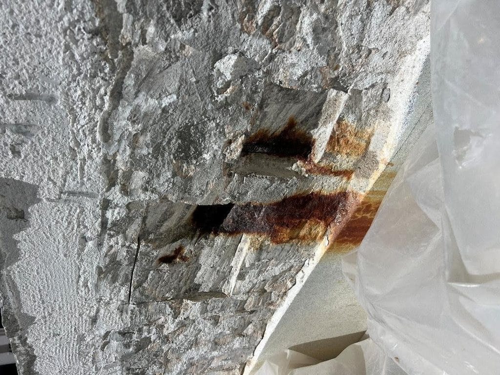
The structural vault functions as part of the home’s building envelope. Any long-term moisture intrusion in this space can lead to reinforcement corrosion, persistent odor, and avoidable maintenance issues. More critically, uncontrolled water migration inside a structural cavity can compromise the integrity of the concrete over time.
The pool shell inside the vault is a completely separate assembly. It holds chemically treated water under constant hydrostatic pressure and must be designed to resist both internal forces and long-term immersion. For this reason, the pool and the vault cannot rely on the same waterproofing system or the same performance criteria.
On projects of this complexity, we treat the two assemblies as independent scopes.
The vault receives a waterproofing system intended to protect the building envelope, control incidental moisture, and prevent water from reaching structural members or occupied areas.
The pool vessel receives a separate cementitious or hybrid waterproofing system formulated specifically for continuous immersion, chemical exposure, and movement tolerance. This system is applied uniformly beneath the tile assembly to create a fully bonded, watertight envelope around the vessel.
Separating the waterproofing systems is not only best practice; it is a diagnostic strategy. If a leak ever occurs, we want to identify exactly which assembly is affected and prevent water from migrating freely through multiple layers of structure. This level of control is essential in elevated pools where access is limited and the consequences of mismanaged water can be significant.
Designing for Condensation Inside The Vault
Not all water inside an elevated vault comes from the pool or from outside. A significant portion comes from the air itself. Once the vessel is built, the space beneath it becomes a relatively cool, enclosed cavity. Above it is a warm body of water. Surrounding it is a hot, humid coastal environment. This combination creates ideal conditions for condensation to form on cooler surfaces within the vault.
If this moisture is not given a way to move, it will accumulate slowly but continuously. Over time, even small amounts of recurring condensation can stain concrete surfaces, corrode embedded metal, and create maintenance issues that appear unrelated to the pool but originate from environmental conditions.
To manage this, we design the vault with a dedicated condensation drainage strategy. This has nothing to do with pool leaks. It is simply acknowledging the physics of a conditioned cavity under a warm waterfront pool. Drainage mats are placed between the foam and the structural surfaces to create channels where moisture can travel. Dedicated drain lines are positioned at low points so any water that forms has a controlled path to reach a collection point or discharge location. In some cases, the slab must be subtly sloped to encourage movement toward those drains.
The objective is not to make the vault perfectly dry, which is unrealistic for this type of coastal structure. The objective is to keep the space predictable and maintainable. By giving incidental moisture a defined path to escape, we prevent the long-term deterioration that occurs when condensation has nowhere to go.
Integrating An Acrylic Window Into an Existing Structure
One of the defining architectural features of this project is the underwater viewing window located on the lower level of the home. The panel itself is built into the pool wall, but for it to function as a true viewing element, a coordinated opening had to be created in the existing structural vault so the interior of the home aligns with the clear face of the acrylic. Achieving that alignment requires careful coordination between the pool structure, the vault, and the house engineering team.
The first step was determining how large an opening the vault wall could safely accommodate without compromising the integrity of the existing structure. Working with the house engineer, we evaluated reinforcement patterns, load paths, and the impact of introducing a new opening. Once the allowable opening size was established, the pool wall was designed around that geometry so the viewing area of the acrylic panel and the opening in the vault aligned precisely.
Designing the pool wall to accept an acrylic panel is a highly technical process. Unlike a standard concrete wall, this assembly must resist hydrostatic pressure without excessive deflection, support the acrylic evenly along all edges, and maintain a watertight transition between materials that behave very differently over time. This requires recalculating wall thickness, reinforcement density, concrete strength, and the exact geometry of the reveal where the panel seats.
The acrylic panel itself must also be engineered for the depth and load conditions of the pool. To determine the correct thickness and support configuration, we use finite element analysis to model how the panel deflects under pressure, where stresses accumulate, and how the material will perform over its service life. The results dictate the required material properties, thickness, and frame geometry to ensure long-term safety and clarity.
Our responsibility is to coordinate these intersecting systems:
- The structural considerations of modifying the existing vault
- The geometric alignment between the house opening and pool wall
- The engineering of the pool shell and waterproofing around the panel
- The long-term load path and safety of the acrylic assembly
When these components are brought together correctly, the window becomes a fully integrated structural feature of the pool. It performs safely, aligns cleanly with the architecture of the home, and provides a reliable underwater viewing experience for decades.


Routing Plumbing and Conduits Through Structural Foam and Into the Home
Although the pool is elevated inside a structural vault, every hydraulic and electrical system still needs to reach the equipment room located on the lower level of the home. This creates a unique routing challenge. The space beneath the pool shell is filled with structural foam used to support the vessel and manage load distribution. That foam cannot simply be cut away arbitrarily, yet it must accommodate every suction line, return line, feature line, conduit, and drainage pathway that serves the pool.
To solve this, the foam layout is planned in parallel with the plumbing design. Channels are intentionally shaped into the foam to create dedicated pathways for piping and conduits while preserving the structural performance of the material. These channels must allow each line to maintain proper pitch, avoid unnecessary elevation changes, and reach the vault wall entry point cleanly.
All routing is developed digitally before any work begins. Using Revit, every hydraulic and electrical run is modeled in three dimensions so we understand how lines move through the foam, how they clear structural elements, and how they arrive at the equipment room. This prevents conflicts, ensures adequate slope, and confirms that each penetration through the vault wall aligns with the equipment layout below. Modeling the system in 3D also allows us to plan for serviceability, ensuring that valves, unions, manifolds, and electrical terminations will be accessible in the long term.
Effective routing in an elevated vessel requires careful coordination:
- The foam must be designed with plumbing pathways integrated into its geometry.
- The compressive expectations of the foam cannot be compromised by unnecessary voids.
- The equipment room layout must be coordinated so incoming lines land exactly where they are intended to connect.
When planned correctly, the routing becomes predictable and efficient. Lines follow logical paths, transitions are smooth, penetrations land in the right locations, and the system is far easier to build and maintain. Years later, technicians can understand the infrastructure without guesswork because the routing was engineered deliberately from the start.

Tile Patterns as a Technical Constraint, Not Just A Finish Material
The pool interior on this project is a fully custom tile package whose pattern echoes the geometry from other parts of the property. The $200,000 cost alone places it in a category where small mistakes are not acceptable.
Before any fittings were coordinated, we developed multiple tile layout options in both two dimensional and three dimensional form. Part of the design effort was understanding how the pool interior could respond to the architecture of the home. The driveway of the property uses a distinctive geometric pattern, and we explored how that language could be integrated into the pool so the outdoor spaces felt connected rather than isolated design decisions. Reviewing these iterations in 3D allowed the client to see how each option read at scale and how the pattern would behave once submerged and viewed through moving water.
For us, that means the tile layout is not simply a finish. It becomes a constraint that drives where we place hardware and fittings. Penetrations like drains, suctions, returns, and lights cannot be dropped into the design after the fact. They have to be coordinated into the pattern so they either align intentionally or disappear.
At the center of the pool is a circular tile motif that reads as the focal point of the interior. A standard square drain grate would have destroyed that composition. Instead, we specified a circular, finish ready drain cover that accepts the same tile material on top. That allowed the functional element to sit exactly at the geometric center of the pattern without visually interrupting it.
The principle is simple. The technical requirements do not get to override the design. They must be integrated into it so the interior reads as a single, deliberate idea rather than a series of unrelated parts.

Why Specialized Expertise Is Essential for Projects of This Complexity
Projects like this one are fundamentally different from standard residential pools. The complexity comes not only from the vessel itself but from the environment in which it must function. Working inside an existing structural vault, on an elevated coastal home, within fixed geometric and load constraints creates conditions that are far more demanding than a typical inground application. Any one of these factors would add difficulty to a standard pool. When they all occur together, they create a project type that requires specialized expertise.
In these situations, understanding how to design a pool vessel is not enough. The team must also understand the disciplines that surround the vessel and how the pool must be engineered in coordination with them. Waterproofing elevated structures, managing condensation inside enclosed cavities, designing around structural foam, and understanding how the pool interacts with the existing building are all separate areas of practice. Yet on a project like this, they directly influence how the vessel must be shaped, supported, and detailed.
Without that broader knowledge, critical elements can be overlooked, and in an elevated residential structure those oversights can become serious long-term issues. Even the acrylic viewing panel must be engineered as both a pool component and a building component to ensure that it remains watertight and structurally sound for the life of the home.
This is why specialization matters. A project like this requires a team who can engineer the aquatic vessel with its own internal requirements while also integrating it into the architectural and structural setting it occupies. When that level of coordination is applied from the beginning, the pool performs correctly, protects the property, and meets the standards expected for a project of this complexity.